COORDINATION STUDY

Coordination Studies
Why do I need a protective device coordination study? Electrical systems commonly use fuses and circuit breakers to protect electrical equipment such as conductors, transformers, motors, and other components. If a failure occurs within this equipment, usually a short circuit results. It would be desirable that this short circuit would affect only that portion of the system where the failure occurs.
In a properly coordinated system the protective devices are selected and adjusted to minimize the impact of equipment failures within a system. A coordination study analyzes the characteristic curves of the fuses and breakers and compares them against one another on log-log plots similar to that shown in the following figure. Any areas of miscoordination will be apparent by overlapping of curves from the various devices.
Most electrical power distribution systems are not planned with protective device coordination in mind. A distribution system can be designed for minimum losses and minimum upfront investment and yet fail in the proper coordination of the protective devices. As a result, equipment failures within the system can easily result in the shutdown of the entire facility. There have been many instances where the failure of a single motor or branch circuit within a building has resulted in the shutdown of most of the facility.
What does a Coordination Study do for me?
A protective device coordination study analyzes the impacts of short circuits and equipment failures within a facility and determines the effects on the facility operation. This study is combined with the Arc Flash Hazard Analysis, which is required by present electrical safety codes and enforcement agencies. Informed decisions can then be made as to the changes necessary for the system.
Objective of Coordination Studies
The goal of a Protective Device Coordination Study is to achieve an optimum balance between equipment protection and selective isolation that is consistent with the operating requirements of the overall power system.
In addition, the interrupting ratings of all protective equipment, conductors, and switches are checked for adequacy in coordination studies. Inadequate equipment ratings can result in either extensive damage to the equipment during faults and system operation and may introduce hazards to plant operating personnel.
|
Short Circuit Study The purpose of the short circuit study is to determine the ability of each component within an electrical system to withstand and/or interrupt the system current. Short circuit studies provide an analysis of all possible operating scenarios which will be, or have been influenced by, the proposed or completed additions or changes to the subject system. Information contained within the study include tabulations of the data used to model the system components and a corresponding one-line diagram. Descriptions of the scenarios evaluated, and identification of the scenario used to evaluate equipment short-circuit current ratings are also included in the study. Tabulations of equipment short-circuit current ratings versus available fault duties can be found in short circuit studies. The study report should identify the percentage of rated short circuit current and clearly note which equipment have insufficient ratings. 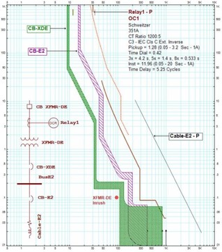 Arc-Flash Hazard Analysis The purpose of the arc-flash analysis is to determine the arc-flash incident energy levels and flash-protection boundary distances of electrical equipment based on results found in short-circuit and coordination studies. The analysis is performed under worst case arc-flash conditions for all modes of operation and provides an analysis of all possible operating scenarios which will be, or have been influenced by, the proposed or completed additions to the subject system. Short circuit and coordination studies are performed to determine the available energy of an electrical system and the expected clearing time of protective devices, the arc-flash hazard analysis selects the working distances and calculate the incident energy at each fault location at the prescribed working distance. Based on this information, the arc-flash hazard PPE category for the calculated incident energy level can be specified along with the flash protection boundary at each fault location. Descriptions of the scenarios evaluated and identification of the scenario used to develop incident-energy levels are included. Arc-flash boundaries and tabulations of the data are found within the study and should clearly identify equipment that exceeds 40 cal/cm2. Any potential system operating modes including tie-breaker positions, and parallel generation are also identified within the arc-flash hazard analysis as these conditions will have an effect on the available incident energy. Stability Studies A stability study determines the ability of the synchronous machines within an electrical system to remain in step with one another following a disturbance. Stability studies provide an analysis of disturbances for all possible operating scenarios which will be, or have been influenced by, the proposed or completed additions or changes to a system. Information contained within a stability study include tabulations of the data used to model the system components and a corresponding one-line diagram. Descriptions of the scenarios evaluated and tabulations or graphs showing the calculation results are also included with conclusions and recommendations by the engineer performing the study. How Data is Interpreted and Applied The data found within power system studies can be interpreted and applied in many different ways depending on the type of study performed and the reasoning behind the study. Coordination studies, for example, are often used by test technicians during acceptance testing in the field to ensure that protective devices are set correctly and performance tested in accordance with the settings specified within the study. Arc flash data is used to generate labels that is applied to system components, informing workers of the available incident energy at a particular piece of equipment and the appropriate levels of Personal Protective Equipment that should be worn while performing work. |
1. Selective coordination Determines the protective device types, characteristics, settings, or ampere ratings which provide selective coordination, equipment protection, and correct interrupting ratings for the full range of available short circuit currents at points of application for each overcurrent protective device. 2. Compromised coordination Determines protective device types, characteristics, settings, or ampere ratings which permit ranges of non-coordination of overcurrent protective devices. In this case, overcurrent protective device coordination may be compromised due to the overcurrent protective devices selected or already installed or in order to achieve protection of equipment that is selected or already installed. Circuit breaker trip time coordination example. Simplified example of circuit breaker coordination. The objective of compromised coordination is to maximize coordination of overcurrent protective devices to extent possible based on the type of devices. Determine protective device characteristics, settings, or sizes which provide a balance between equipment protection and selective device operation that is optimum for the electrical system. Information contained within a coordination study include a system one-line diagram along with Time-current curves, selective coordination ratios of fuses, or selective coordination tables of circuit breakers demonstrating the coordination of overcurrent protective devices to the scope. Coordination studies also include tabulations of protective devices identifying: Circuit location Device manufacturer and type Current transformer ratios and Range of adjustment IEEE device number Recommended settings or device size Referenced time-current curve Arc-Flash Hazard Analysis The purpose of the arc-flash analysis is to determine the arc-flash incident energy levels and flash-protection boundary distances of electrical equipment based on results found in short-circuit and coordination studies. The analysis is performed under worst case arc-flash conditions for all modes of operation and provides an analysis of all possible operating scenarios which will be, or have been influenced by, the proposed or completed additions to the subject system. 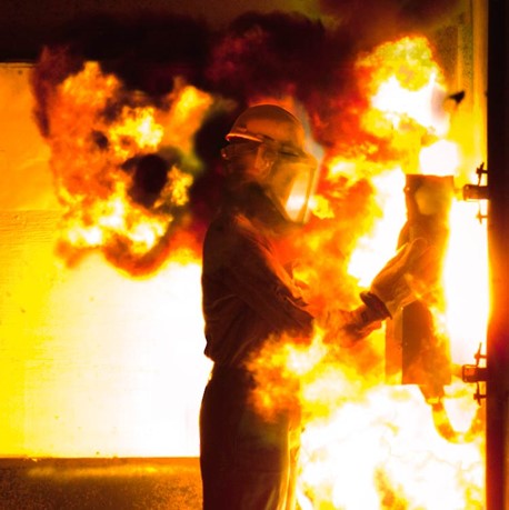 Load Flow Studies A load flow study determines the active and reactive power, voltage, current, and power factor throughout an electrical system. Load flow studies provide an analysis of all possible operating scenarios and identifies overloaded equipment. Included within the load flow study is a tabulation of the data used to model the system components and a corresponding one-line diagram. Descriptions of the scenarios evaluated and the basis for each are also found within the study, along with: Tabulations of power and current flow versus equipment ratings – Identifies the percentage of rated load and the scenario for which the percentage is based, noting any overloaded quipment within the system. Tabulations of system voltages versus equipment ratings – Identifies the percentage of rated voltage and the scenario for which the percentage is based, noting voltage levels that fall outside the ranges recommended by equipment manufacturers. Tabulations of system real and reactive power losses, noting areas of concern along with conclusions and recommendations from the engineer performing the study. How Data is Collected Complete and accurate data pertaining to the system to be analyzed is essential for power system studies. Newly installed systems may have studies performed using project drawings and specifications while existing systems require data to be collected in the field. Data is often recorded directly from the nameplate of equipment in service. Obtaining power system data in the field should only be performed by qualified personnel as this work often involves removing access panels on energized equipment in order to obtain information not found on the nameplate, such as cable sizes and number of feeders. 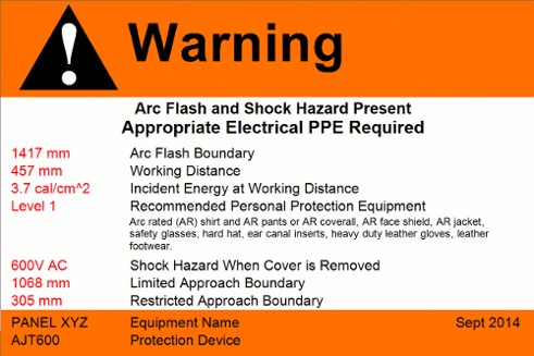
|